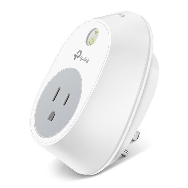
I had a few devices in my apartment that I wanted to be able to turn on and off from my computer. I found that there exists a type of product called a "smart plug" which connects to Wi-Fi, and plugs into the wall, and has an AC power socket which you then plug your device into, and the Smart Plug will then be able to turn your device on and off upon receiving a command over Wi-Fi. Neat!
Unfortunately, most of these rely on proprietary apps, and most of these apps are only available for phones. For me, this simply won't do - I wanted to be able to operate them from my Linux computer. I also didn't want to have the devices be controlled by an external server that the manufacturer operates - this is for a few reasons. One is that if the server should ever shut down, the devices may be rendered inoperable. Another is that I don't want anyone else getting data over my network which might include the possibility of hacking. I don't want this Smart Plug to be an opportunity to get attacked. So ultimately, I want to connect them to Wi-Fi, without them needing access to the outside internet.

I found the TP-Link HS100 (and related models), which have had their network protocols analyzed and replicated. There are now projects to generate the necessary packets on a computer running a Python script, rather than coming through the app. I personally used this option: https://github.com/softScheck/tplink-smartplug All I need is the .py file there and it serves my needs. I've blocked the MAC address of the plug from accessing the internet (through my router's control panel) so it truly is local-only control.
So I've been using one of these for a while, and decided to order a couple more on eBay - these appear to be out of production, and I don't know of any currently-produced models that allow for local control.
I decided to crack one open and see what's inside, and most interestingly, see if I could find a UART shell.
Part 1: Inside the Device
So the first order of business is to get this thing open. I started by googling for a teardown, at which point I found: https://www.edn.com/teardown-a-wi-fi-smart-plug-for-home-automation/
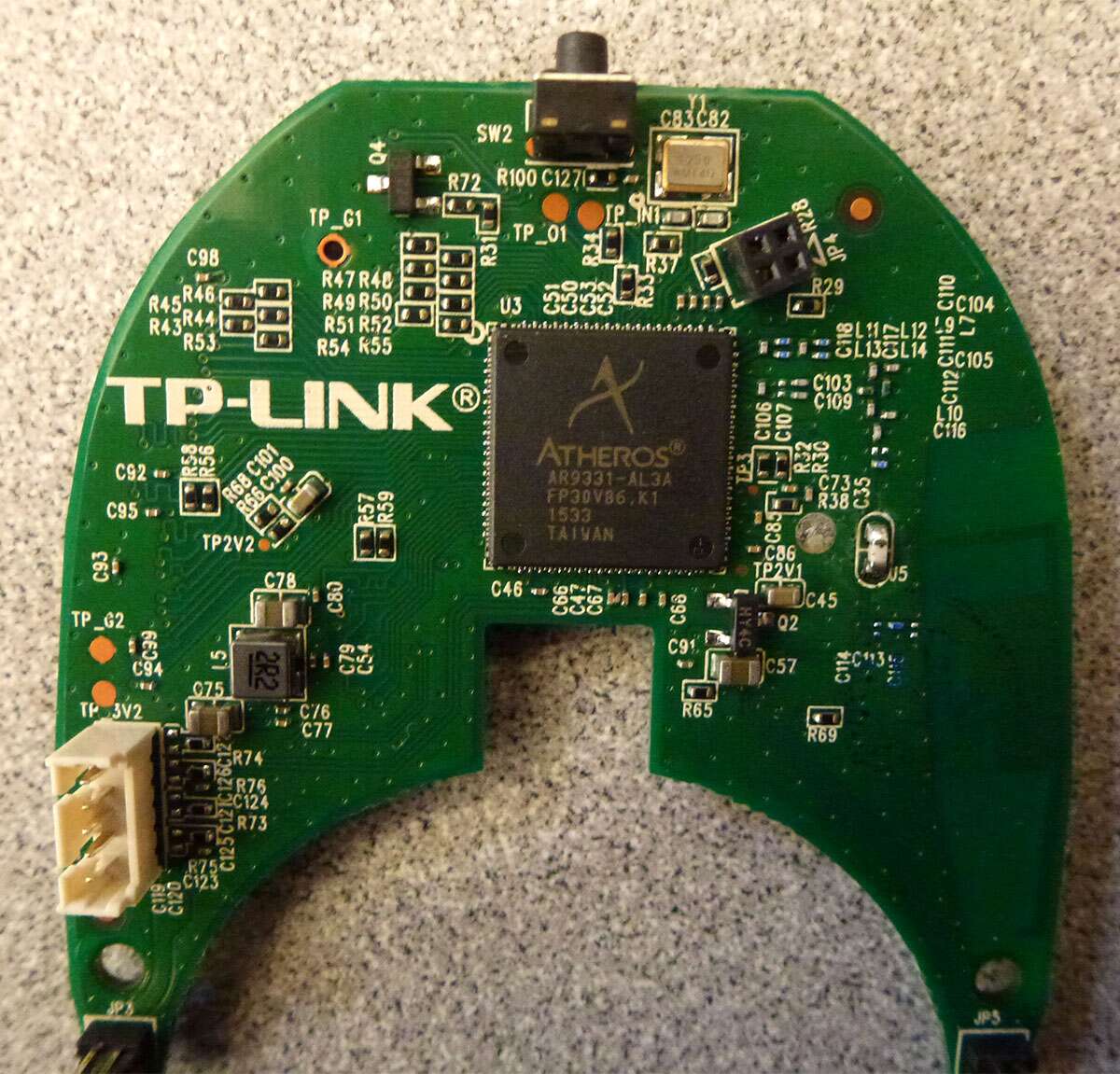
This has some nice high-quality images. Particularly, the image of the main digital board was intriguing.

I immediately noticed JP4 on the upper right, as well as a white connector on the left edge. These both had 4 pins, which suggests to me they might be UART connections. This definitely indicates that this thing is worth further investigation. I went ahead and opened up my unit, and found a surprise. I believe EDN's teardown was hardware revision 1, while mine is revision 2 (the sticker on the back says "Model: HS100(US) Ver:2.0"). The insides are quite different from EDN's.
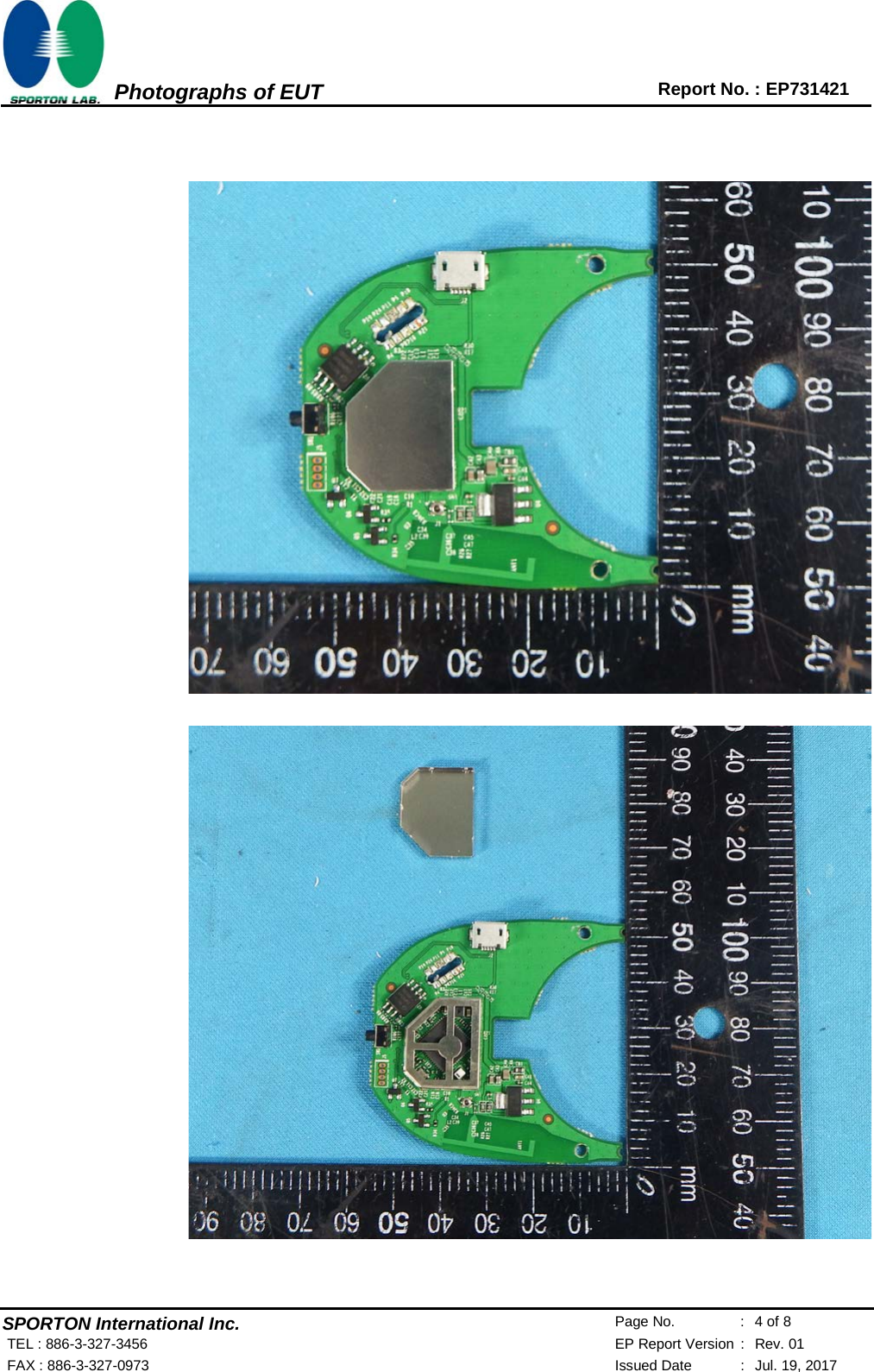
I didn't think of this before taking it apart, but now, writing this, I realized that my device has an FCC ID of "TE7HS100V2". Note the V2 at the end - EDN's photos don't have this. Looking up that FCC ID gives us a great set of internal photos: https://fccid.io/TE7HS100V2/Internal-Photos/Internal-Photos-3476540
My unit is identical to these photos. The two 8-pin connectors with tall headers connecting them have been replaced by a simple vertical PCB bridging between the two. It appears to have 10 contacts. Most notably, this version of the PCB has a set of 4 pins, in this photo shown on the far left edge, right below the button:

Now that looks like a UART to me.
Part 2: UART hacking
So now I started probing that port. I quickly found that the third pin (where pin 1 is adjacent to the white stripe on the silkscreen outline of this header) was ground.
I then connected my Saleae Logic Analyzer to the remaining 3 pins, and saw activity coming out of the second pin.